top of page

Lim Choon Wah, Reeve
Architecture E-Portfolio
Project 2A: Building Moedling
From this assignment I need to understand and apply Revit Architecture's modeling tools to generate a building model. Hence, the production of Revit model of the selected architecture design using Architectural Components such as Wall, Roof, Stairs, Floor, Curtain Wall, Doors, Column, Windows. The building I chose is from Brazil design by the Architect name Oscar Niemeyer in 1951 as his family home. The building name is Casa Das Canoas and is considered one of themost significant examples of modern architecture.

tumblr_static_casa_das_canaos

openhouse-barcelona-shop-gallery-architecture-oscar-niemeyer-casa-das-canoas-rio-de-janeiro-2

images

images(3)

images

images(7)

untitled(5)

images(4)

7cn

Capture

2

3

4

5
Starting
In beginning, I need to start up everythings before started to design a building
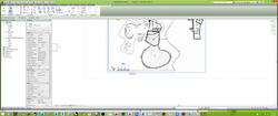
 1Create a wall by adding a line |  2Fillet arc on the corner of the wall |  3In place a mass to create a curve wall |
|---|---|---|
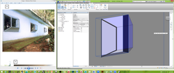
 4Draw with spline to create curveness | 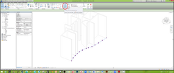 5Click the create form to extrude the wall | 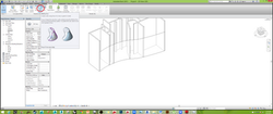 6Click the wall on Massing & site category |
 7The curve wall had been formed |  8The type of curve still can be change |  9Using the same method to create another curve wall on ground floor |
 10This was the 3D of the new curve wall |  11Than, create all wall on the ground floor |  12We can choose unconnected height to first floor, it will auto reduce the height to reach the limit or can using attach top base. |
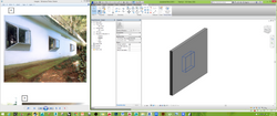
 13Create a hole by edit the wall. than create another circle it will auto boolean | 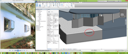 14After edit, the hole had been formed between the wall |
1) Wall
The wall creation is much more faster than in autocad, 3ds max and rhino. Hence, it also able to auto join the wall when it meet each other or intersect without trimming like traditional software. It was a win-win method which save time and precise.
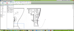
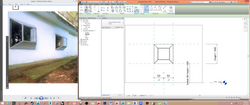
 1Create an architecture template |  2Insert an plan to trace the building | 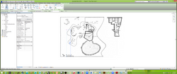 3Use wall or model line to measure before scale up |
|---|---|---|
 4After put a correct measurement | 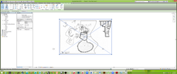 5Scale up into a proper dimension |  6Copy to clipboard so that could recopy a new image onto other plan view |
 7Adjust the elevation height and create new floor |
2) Floor
To create floor, we not just only must create a line to trace. We still can pick the line and choose the wall, it will auto create the line after chosen. That speed is unbeaten.
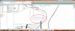
 1Click floor on architecture category to create a slab |  2We still can change the floor type on properties tab |  3The floor had been formed can be shown in 3D |
|---|---|---|
 4Create another floor slab on ground floor by using pick lines |
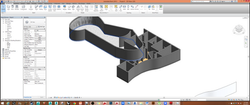
3) Roof
The roof is able to create curve by using spline and it can set a limit for the wall to avoid extrude above the roof. It save the time on trimming the extra extrude wall.
 1Create the roof by using spline to make curve wall | 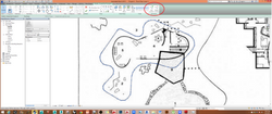 2After done we still can edit such as move, add or delete the point. |  3After all the process, the curve roof had been formed, eventually it still can change it roof type. Hence, we still can select the wall to add top/base to the roof to control the wall height. |
|---|
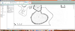
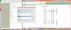
4) Stairs
Stair was one of the complicated and waste time because it needed to calculate in tradional software. While in Revit it saves people such as it will auto generate and calculate the riser, thread, thickness in short time. So we dont need to squish our brain juice.
 1Create a staircase by using run | 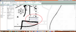 2Click a point than pull it and determine how many thread I needed. |  3The staircase had been form but the floor had been blocking to walk up, so needed to create an opening by using shaft. |
|---|---|---|
 4Create a shaft opening on architecture category, using pick lines and lines to create an opening. |  5The staircase and opening in 3D |
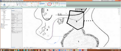
5) Pool
Using shaft opening to boolean it to create a pool in no time and enable to edit the shape of shaft opening.
 1Create a shaft opening for making pool |  2Adjust the height of shaft opening |  3Create a mass than transform to floor |
|---|---|---|
 4The mass will boolean the wall to create a hole |  5The hole had been appear |  6Create another mass to create pool |
 7Pick the lines and offset when create the mass |  8Transform the mass into floor and adjust the height | 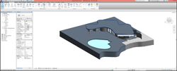 9The pool had been create |
6) Column
Column is a structural component, it can be auto place on each level u need and what the height of it by using unconnect to which level.
 1Create a column on structural category, if want to change a new column. Enter the edit type and choose load and find column category. Than choose the column needed. |  2Can change the column type on properties tab and remember using vertical column unless need to make slanted column |  3It can be copy to move on another side to support the roof |
|---|
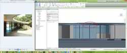
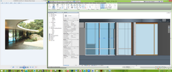
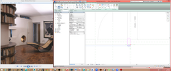
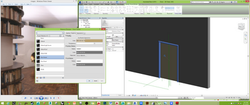
6) Curtain Wall
Curtain wall is the favourite architect component in modern era, in Revit u can just simply choose the linear wall or even curve wall and choose storefront it will auto generate and be adjust the distance on horziontal and vertical spacing. Hence, It also can be auto generate them mullion. This was one of my favourite component in Revit.
 1Loading a double sliding panel from the door category |  2Insert the door into wall, it will auto generate and adjust the height and length |  3This is plan view of the door |
|---|---|---|
 4Select the wall to convert to storefront |  5Unpin it so the mullion can be deleted | 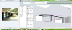 6Adjust the wall profile |
 7Unpin again to delete unwanted mullion |  8Create another small pieces of wall | 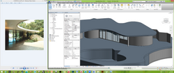 9The left elevation side of curtain wall had done |
 10Pick a line and create the form to make wall | 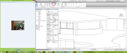 11Applied the massing wall on lower part | 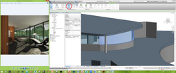 12Applied curtain system on upper part |
 13Click the create system to form panel |  14Adjust the fixed distance on each panel glass |  15Can be adjust on properties tab also |
 16To create mullion by adding from grid lines |  17The mullion had been create |  18The front elevation of curtain wall had been create |
 19Unpin it |  20Convert to glass to glass door | 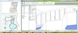 21The glass door had been converted |
 22create segment on curtain wall to add mullion |  23Right elevation of curtain wall had been done |
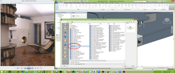
Revit Family Components
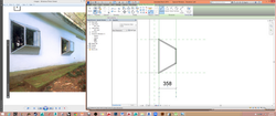
Revit also famous in parameter where autocad and 3ds max cant be doned but still rhino can be work in grasshopper or others plugin. In this assignment I had create 3 family which are taper cube window, door and doorknob. It took a time to learn how to add parameter by using refrence line and can be adjust to any length, width, height of the component.

Taper Cube Window

Doorknob

Door
Taper Cube Window
Create a new familiy componenet by choosing metric window. I had make a custom form of window by using blend to create taper cube-shaped and loaded into the building. I also make sure that the window is avaible to para on the length, width and height.
 1Create a new family for edit a custom window |  2Choose metric window |  3Choose blend to create taper cube form |
|---|---|---|
 4Than rotate the form to align with the direction of wall |  5Adjust the top base to create taper |  6Pick a plane on selected object, so anything will work on that plane |
 7Assign glass material on glass |  8Choose sweep to prepare sketch a path | 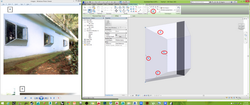 9Than lock the line after pick the line on the edge of glass |
 10than choose the profile of Square Rail 20mm or create own profile |  11Create another frame on another side of window | 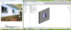 123D view of the full frame |
 13Create another extrusion on top of window as shading devices |  14Than move all the edges of taper cube window on each side to lock it. so that it could be parametric |  15 |
 16 |  17 | 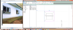 18 |
 19 |  20 |  21Create another dimension align on both reference line |
 22create an equal trasnform when increase the width |  14 (30) | 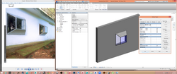 24Ready to check whether could be transform in family types |
 25It had success trasform |  26 |  27 |
 28 | 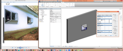 29It had success transform | 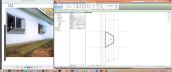 30Create a reference line |
 31Create a parametric of window width |  32Remember to lock it between the ref lines and window | 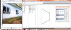 33Decrease the width of window |
 34It success trasnform |  35Create another extrusion on bottom |  36Create reference line |
 37Add parameter of outer window width rightward |  38 |  39Add parameter of outer window heigth rightward |
 40 | 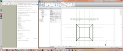 41 |  42 |
 43 | 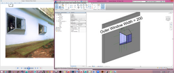 44Final of taper cube window |  45Plan view of the window |
 46loaded window onto the building |  47Final taper cube window on the building |
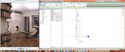
Door Knob
Create a door knob by using generic model family. Using revolve the create by adjusting the boundary line and axis line.
 1Create a revolve, purple is the boundary line and blue is axis line. |  2The drawing had done to ready become 3D door knob |  3Load the 3D door knob load into project (door) |
|---|---|---|
 4The door knob had been loaded, need to be rotate | 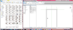 5Elevation view of door | 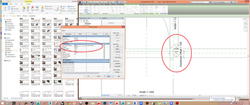 6Adjust the doorknob offset and adding the formula |
 7Same applied to doorknob offset ext |
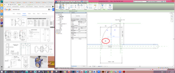
Parametric Door
The door was quite a like as window. Create a door by using sweep for the frame and extrustion for the panel. Than add in reference line for add parameter to adjust any number I like in future.
 1Select metric door family | 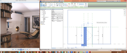 2Create a reference line to add parameter |  3Add frame width of 75mm |
|---|---|---|
 4Add another reference line on left |  5Lock the locker once applied the reference line |  6Assign dimension to make it equal |
 7Frame had been create | 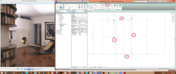 8Lock the line once |  9Adjust the extrusion thinkess and lock it |
 10Add another parameter of the panel | 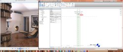 11The panel thickness was 40mm |  12The panel had been create |
 13Create panel in 2D |  14Create Arc line |  15Adjust the width to check whether it can be moved |
 16Un tick all visibility settings |  17Create sweep along the frame line and choose sketch path |  18Lock the line so it can be move when adjust the width and heigth |
 19Drawing the profile to allow sweep |  20After sweep in 2D plan | 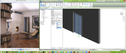 21Assign the panel into sub category |
 22Assign material color also |  23Load doorknob into door | 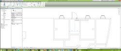 24Than load the door into the building but the doorknob was shown |
 25Need to un tick the visibility setting | 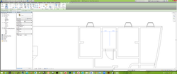 26Doorknob gone but can be view in 3d |  27This was the parametric door with doorknob |
bottom of page